#Pulse Width Modulating
Explore tagged Tumblr posts
Visit Tumblr Blog
Explore Tumblr blogs with no restrictions, modern design and the best experience.
Last Seen Tumblr Blogs


Fun Fact
Hackers stole 65M passwords from Tumblr in 2013.
Text
Sähkömoottorin kaasupolkimen suomalainen isä Martti Harmoinen on poissa — Helsingin metrosta tekniikka levisi teollisuuteen, sähköautoihin ja hisseihin
Taajuusmuuttaja - Wikipedia
#Helsingin Sanomat#Martti Harmoinen#Muistokirjoitus#Tekniikan Maailma#Taajuusmuuttaja#Strömberg#ABB#Variable-frequency drive#Pulse Width Modulating#PWM#obituary#in memoriam#rest in peace
1 note
·
View note
Text
不都合な真実
アナログレコードプレーヤーーー>CDプレーヤ
しばらく長い間イノベーションが無かったオーディオ業界にとって、デジタルで音楽を再生する(DA変換)というアイデアはビジネスとして圧倒的なDriving Forceとなった。ユーザ(顧客)にとっても22KHz以上の帯域がカットされていいのか?という疑念よりもメディア(盤)面のキズやホコリから解放されることのほうが重要だったのだ。しかしこの時点では、音楽プレーヤという<周辺機器>で起こったイノベーションにとどまった。いうまでもなく、<本丸>はパワーアンプである。
A級、AB級ーーー>D級(PWM)
しばらく長い間イノベーションが無かったオーディオ業界にとって、パルス幅でスピーカを駆動する(PWM)というアイデアはビジネスとして圧倒的なDriving Forceとなった。なぜなら歴史的に最も物量を投入してきたパワーアンプを(特に筐体にこだわりがなければ)1kg未満に仕上げることが可能になるのだ。これはAmazonでパワーアンプを気楽に何個も発注して楽しむ時代の到来を意味するとともに、特に日本のオーディオメーカにとっては冬の時代の到来となった。時計で起こったことが、オーディオでも同じように起こったのである。
An Inconvenient Truth
#audio#watch#innovation#digital#analogy#analog#power amplifier#class d#disruptive innovation#pulse width modulation#pwm#clock#an inconvenient truth
1 note
·
View note
Text
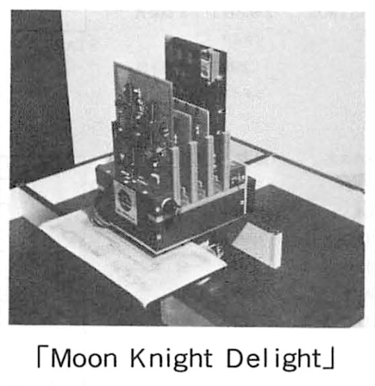
Moon Knight Delight (1985) by Baxter Cheung, California State University, CA. Another Competitor at the 1985 World Micromouse Contest held in Tsukuba '85, Japan, is 'Moon Knight delight'. It came first at the '85 United States Micromouse Contest. It's not fast, but it can negotiate a maze reliably. The motors are driven using Pulse Width Modulation (PWM), sometimes referred to as "chopped drive" with a sound familiar to anyone who's listened to the sing-song of a 3D printer. "The US mouse clearly used a chopped drive to its motors. The sonic effect was one of advanced rust, as the mouse squeaked and groaned through the maze." – Micromice at Expo 85, Tsukuba, by John Billingsley.
The video is an excerpt from "The first World Micromouse Contest in Tsubuka, Japan, August 1985 [2/2]."
#cybernetics#robot#micromouse#California State University#1985#'85 World Micromouse Contest#'85 United States Micromouse Contest#maze solvers
24 notes
·
View notes
Text
"See" the Sounds of Classic Mac Audio 🔊🍏
We're working on the Pico-Mac port https://github.com/jepler/pico-mac/tree/rp2350-fruitjam to Fruit Jam https://www.adafruit.com/product/6200 and one thing we really want to add is sound support for classic Mac games and HyperCard stacks.
Audio on the hardware we're emulating is pretty straightforward: every scanline of the video generator also outputs one byte of PWM (Pulse Width Modulation) data. We have 370 horizontal lines—352 visible and 18 during the vsync—at a 60.15 Hz refresh rate, producing approximately 22.255 kHz audio. That data is written to memory address $1FD00 http://www.mac.linux-m68k.org/devel/plushw.php so all we have to do now is pipe that 8-bit PWM signal either out to a timer on the RP2350 microcontroller or To the TLV320DAC3100 I²S amplifier onboard Fruit Jam, for that sweet, sweet 'Wild Eep' https://www.facebook.com/adafruitindustries/videos/1873371666122621
#marchintosh#classicmac#retrogaming#pwm#macintosh#hypercard#fruitjam#adafruit#raspberrypi#hardwarehacking#opensource#vintagecomputing#soundemulation#makers#electronics#diytech#audioprogramming#rp2350#macaudio#emulation#retrohardware#techinnovation#embeddeddevelopment#circuitpython#engineering#programming#linux#python#java#software engineering
18 notes
·
View notes
Text
Mega-update!

What is new in the latest release:
Customizable wheels! Wheels can be changed in Paint Shop menu, just pressing a button "Wheels". Wheels can be textured with carbon fiber (with color alpha). One of wheel model has invalid UV with stretched carbon fiber in the middle, don't see it :)
Awesome mouse clickable HSV and HSVA color pickers!
Lap highscore is visible in spectator mode (on server and standalone modes). Clients don't see a highscore now, request-respond things will be later.
Variable strobe width on penalty warn. Yellow taillight warning pulse-width modulation.
Hide UI in the paint shop. Unhide on any button (not WASD, analog and Ctrl/Alt/Shift).
Switch online subsystem: Steam/LAN. Last option stored in the save file.
Updated axis parameters widget, and custom horizontal slider. Awesome horizontal sliders, are based on a border with text. LMB Drag - scrolling, RMB - reset.
Main Menu: "PC does not support SM6 warning" message. The game works with DX11, but with some visual glitches. It may be fixed in the future. However, the game runs at 60 FPS on and old laptop with GeForce GTX 960M (low settings with shadows on).
Fix crash on exit race in spectator mode.
Fix mouse disappear in menu for no reason. I found a reason, fixed.
Other boring C++, Blueprint and shader things for things above.
13 notes
·
View notes
Text
cant stop listening to witch house….. 5:11am…. going back for more pulse width modulation
7 notes
·
View notes
Text
It works!*
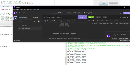
So I (FINALLY) put the final touches on the software for my robot PROTO! (Listen, I am a software person, not a coming-up-with-names person)
Basically, it is a ESP32 running him. He takes HTTP messages. Either GET odometry, or PUT twist. Both just being a string containing comma separated numbers
Odometry is the robots best guess based on internal sensors where it is (Since PROTO uses stepper motors, which rotates in tiny tiny steps... it is basically counting the steps each motor takes)
Twist is speed, both in x,y and z directions, and speed in angular directions (pitch, roll and yaw). This is used to tell the robot how to move
Now, since PROTO is a robot on two wheels, with a third free-running ball ahead of him, he cannot slide to the side, or go straight up in the air. You can TRY telling him to do that, but he will not understand what you mean. Same with angular movement. PROTO can turn left or right, but he have no clue what you mean if you tell him to bend forward, or roll over.
The software is layered (Which I use a BDD diagram to plan. I love diagrams!)
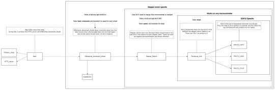
Basically PROTO gets a twist command and hands that over to the Differential_Movement_Model layer.
The Differential_Movement_Model layer translate that to linear momentum (how much to move forward and backwards) and angular momentum (how much to turn left or right). combines them, and orders each wheel to move so and so fast via the Stepper_Motors layer.
The Stepper_Motors turns the wanted speed, into how many steps each stepper motor will have to do per second, and makes sure that the wanted speed can be achieved by the motors. It also makes sure that the wheels turn the right way, no matter how they are mounted (In PROTO's case, if both wheels turn clockwise, the right wheel is going forward, and the left backwards.). It then sends this steps per second request down to the Peripheral_Hub layer.
The Peripheral_Hub layer is just a hub... as the name implies, it calls the needed driver functions to turn off/on pins, have timers count steps and run a PWM (Pulse-width modulation. It sends pulses of a particular size at a specific frequency) signal to the driver boards.
Layering it, also means it is a lot easer to test a layer. Basically, if I want to test, I change 1 variable in the build files and a mock layer is build underneath whatever layer I want to test.
So if I want to test the Stepper_Motors layer, I have a mock Peripheral_Hub layer, so if there are errors in the Peripheral_Hub layer, these do not show up when I am testing the stepper motor layer.
The HTTP server part is basically a standard ESP32 example server, where I have removed all the HTTP call handlers, and made my own 2 instead. Done done.
So since the software works... of course I am immediately having hardware problems. The stepper motors are not NEARLY as strong as they need to be... have to figure something out... maybe they are not getting the power they need... or I need smaller wheels... or I will have to buy a gearbox to make them slower but stronger... in which case I should proberbly also fix the freaking cannot-change-the-micro-stepping problem with the driver boards, since otherwise PROTO will go from a max speed of 0.3 meters per second, to most likely 0.06 meters per second which... is... a bit slow...
But software works! And PROTO can happily move his wheels and pretend he is driving somewhere when on his maintenance stand (Yes. it LOOKS like 2 empty cardboard boxes, but I am telling you it is a maintenance stand... since it sounds a lot better :p )
I have gone over everything really quickly in this post... if someone wants me to cover a part of PROTO, just comment which one, and I will most likely do it (I have lost all sense of which parts of this project is interesting to people who are not doing the project)
129 notes
·
View notes
Text
Pulse-width modulating your robotgirl gf to approximate the desired output amount. What is she putting out? Uhhhhh
#the post about edging pasta with an induction stove that i cant find :(#thanks for leading me to this conclusion
7 notes
·
View notes
Text
Why are LED headlights more visible than classic headlights under sunlight?
LED headlights are more conspicuous in sunlight than traditional halogen or xenon headlights, mainly due to the following scientific principles and design advantages:
High color temperature matches the sunlight spectrum
Color temperature characteristics:
The color temperature of LEDs is usually 5000K-6500K (cold white light), close to midday sunlight (5500K), and has a high overlap with the natural light spectrum. Traditional halogen lamps have a lower color temperature (3000K-3500K, yellowish), and are easily drowned out by ambient light in sunlight.
Human eye sensitivity:
The human eye is most sensitive to 555nm wavelength (yellow-green light), but in sunlight, high color temperature blue-white light (450-500nm) is more easily perceived because it forms a higher contrast with the sky background (Weber-Fechner law).
Ultra-high brightness and luminous efficiency
Luminous flux density:
The brightness of a single LED lamp bead can reach 200-300 lumens/watt (halogen lamps are only 20-30 lumens/watt), and the light intensity per unit area (candela/square meter) is 3-5 times higher. For example, the total luminous flux of a certain LED headlight is about 4000 lumens, while the halogen lamp is only 1500 lumens.
Light saturation resistance:
The ground illumination under direct sunlight is about 100,000 lux. Through the focusing design, the local light intensity of LED can reach 20,000 candela (cd), while the halogen lamp is only about 8000cd. The former is easier to break through the interference of ambient light.
Precise beam control technology
Microlens array (MLA):
The LED chip integrates thousands of micron-level lenses to focus the light into a parallel beam with a divergence angle of 0.1°, reducing scattering losses.
Active matrix control:
For example, Audi's Matrix LED system dynamically enhances the brightness of specific areas (such as road sign reflection areas) under strong light by independently controlling 64 LED units.
Spectrum optimization and penetration
Blue light excitation phosphor:
LED excites YAG phosphor with 450nm blue light to emit broad-spectrum white light. Its short-wavelength component (blue-violet light) is easier to penetrate haze under Rayleigh scattering, improving long-distance recognition rate under sunlight.
Color rendering index (CRI):
LED's CRI>80 (halogen lamp CRI≈100). Although the color rendering is slightly inferior, the high CRI reduces the contrast under strong light. The "unnatural light" characteristics of LED unexpectedly enhance recognition.
Dynamic response and flicker suppression
Nanosecond response:
LED turn-on time <100ns, when the vehicle is bumpy or the sun is flickering, it can maintain stable light output. Traditional filament bulbs have a thermal inertia of 100-200ms, which is prone to residual visual blur.
PWM dimming technology:
Through 1000Hz high-frequency pulse width modulation, while maintaining brightness, the human eye can avoid stroboscopic perception and enhance dynamic visual capture capabilities.
Thermal management advantages
Low temperature operation:
The LED junction temperature is controlled below 85°C (halogen filament reaches 2500°C) to avoid light decay caused by high temperature. Under the scorching sun, the LED brightness decays by only 3%/1000 hours, while the halogen lamp decays by 15%/1000 hours under the same conditions.
Empirical data
Contrast test (ISO 16505 standard):
Under 100,000 lux simulated daylight, the recognition rate of LED headlights at 100 meters is 92%, while that of halogen lamps is only 68%.
Accident rate statistics (NHTSA report):
Vehicles equipped with LED daytime running lights have a 24% reduction in the rate of multi-vehicle collision accidents during the day, while traditional lighting groups only reduce it by 8%.
Conclusion LEDs break through the background noise of sunlight through high color temperature spectrum matching, ultra-high light efficiency, precise optical design and dynamic response, achieving an "optical breakthrough". This advantage not only improves safety, but also promotes the evolution of automotive lighting towards intelligent light field control.

#led lights#car lights#led car light#youtube#led auto light#led headlights#led light#led headlight bulbs#ledlighting#young artist#laser headlights#headlight bulb#headlamp#headlight#american cars#classic cars#cars#car culture#car#car lamp#car light#suv#vehicle#automobile#lamp#halogen#poultryfarming
2 notes
·
View notes
Text
パワー・エレクトロニクス分野における省エネ化の位置付け
小型化と省エネ化は、現代のパワー・エレクトロニクス分野における最大のテーマでしょう。この二つの課題を克服するには、機器の中でもっとも消費電力の大きいアンプや電源を高効率化する必要があります。しかし、従来のリニア方式アンプは、消費電力が大きい、発熱が大きく大型の放熱器が必要、バッテリのもちが悪いなど、多くの欠点があります。
この欠点を克服する電力増幅回路がD級アンプです。D級アンプは、パワーデバイスをスイッチング駆動することで、80%を超える高い変換効率を実現します。この技術を利用すれば、放熱器の小型化や長時間のバッテリ駆動が可能になるのです。
本書は、D級アンプの設計テクニックと製作事例を集大成したものです。D級増幅段の回路設計法から、LCフィルタ、負帰還技術、市販の制御ICの使い方まで、実践で役に立つ知識を実験を交えながらわかりやすく解説します。
ーーーーー
D級/ディジタル・アンプの設計と製作
高効率に電力を増幅できるパワー・アンプの作り方のすべて
本田潤<編著>
CQ出版社
0 notes
Text


Three-Wheeled robot (1985) by Matt Bennett, Maryland, is "based on something I saw in some book - a cool concept, with three (PWM speed controlled) wheels, with smaller wheels mounted on those wheels, you can have the robot move in any direction. ... If you look closely, you can see that each of the larger wheels has a smaller, freely rotating wheel. The three wheels are located 120° around the body. They were each controlled with a simple PWM (Pulse Width Modulation) speed control, with 16 speeds. This was before I learned about nifty concepts like closed loop feedback systems. Hey, I was in 11th grade. There were also simple direction controls so each wheel could go in either direction at a wide range of speeds." – Matt Bennett
22 notes
·
View notes
Text
Medusa-Class Battleship

Creator: Thai'Qul Length: 798 Meters Width: 378 Meters (Widest Point); 70 meters (Narrowest Point) Propulsion: Nuclear Pulse Drive; Five Fusion Drive Thrusters Crew Complement: 5,000-7,000 (Normal complement); 10,000 (Max. Capacity) Radiator Type: Solid-State/Droplet Armaments:
x8 40mm Point Defense Cannons (PDCs) (Aft)
x4 Cargo/Torpedo Bays (Aft)
x2000 5-kiloton driver warheads (Aft)
x4 Ultra-Relativistic Electron Beam (UREB) Cannons (Bow)
Interior
Because the Thai'Qul are an aquatic species, their ships are unique in being almost entirely filled with water. This pulls triple duty in protecting the occupants from intense G-forces, radiation and heat; providing resources for the fusion reactor and torpedoes, and in the event of a hull breach, lost water can be more easily retrieved than air. The consequence of this is that it increases the ship's overall mass, requiring more energy for any kind of acceleration or deceleration. This is also another reason for their ruthless pragmatism: the lack of air pockets outside the cargo sections prevents them from easily taking prisoners or taking larger ships aboard.
Creators
An average Thai'Qul male. Roughly 85% of the species is male, carrying out tasks for the rarely-seen matriarchs, who outsize them significantly. On ships such as the Medusa-class, prepubescent matriarchs- referred to colloquially as "Countesses"- serve the role of captains and admirals.
Strategic Overview
If there's any way to describe the Thai'Qul military doctrine, it would be ruthless pragmatism. Rather than engaging in widespread power projection, heavier ships are mostly concentrated within their own systems, while smaller vessels are the most commonly encountered. These represent the first line of defense, focused on patrolling defense perimeters.
Should a perimeter be broken and an enemy force infiltrate a Thai'Qul system, either by evading or destroying lighter vessels, this is when battleships such as the Medusa-class are deployed. This typically follows barrages of Thai'Qul frigates and corvettes, which will try to guide invaders into designated kill zones, where the Medusa-class will engage them at close range, such as near large asteroids, space stations or ring systems.
While these battleships lack high speed or fine maneuvering, they make up for it with powerful defenses and overwhelming firepower, particularly their UREBs. Once the invader's shields and other defenses have been exhausted, should they refuse to surrender, attacks from these beams will irradiate and effectively sterilize the target.
This is done because, rather than simply blowing up bellicose ships, the Thai'Qul will always try to salvage as much technology and information from them as possible, either to assess motivations or reverse-engineer whatever they discover. Of course, should a ship surrender instead, the Thai'Qul will gladly accept, taking the time to analyze captured ships just as thoroughly.
This doctrine has proven to be quite effective in multiple engagements and ensured invasions of their systems are rare.
Ship Diagram
The Bow Shield is a large dome entirely covered in ablative heat-resistant armor.
The nose of the craft houses the four UREB cannons, which cover a large hemispherical field. While the beams lose effectiveness over time or when fired at an angle, time dilation effects prevent them from completely dissipating over longer ranges. Maximum energy from the bremsstrahlung resulting from impact has been measured at over 5,000 Sieverts.
The UREBs are only possible via the battleship's length, where the linear accelerator (Linac) runs along the central axis of the ship.
The Medusa-Class doesn't have a designated bridge or command module, but instead 36 large windowless spheres, where most of the crew resides. Commands, controls and sensor readings are instead performed using holographic display interfaces that crew members can pull up at any moment. This ensures damage to one area of the ship will not compromise control, and that key staff can be moved into the interior.
The ship uses a combination of solid-state and droplet cooling with liquid lithium, firing the molten coolant into space, where it condenses into larger drops before being recaptured in a dish section for recirculation. Additional radiators vent excess heat to prevent the lithium from completely vaporizing. In times of duress, this coolant can be used as everything from makeshift flares to additional thrusters.
The aft section consists of a large octagonal cylinder, which houses bay sections designed to be drained of water so cargo, torpedoes and other craft can be sent into space. This is also where the ship's fusion reactor is housed.
The PDCs, nicknamed "Barnacles," allow the ship to fire at targets behind or beside the ship.
Contrary to popular belief, the piston supports are only painted blue and not transparent, though they are full of water to help cushion the impact following a pulse.
The pistons and their shock absorbers are attached to a set of electric motors, which extract a small, but not insubstantial amount of power from every pulse.
The Drive Cone is fitted with flexible rings and is even colored bright white to take advantage of as much radiation pressure as possible. Usage of this drive is why the battleship can't be used in a planetary orbit, as the risk of creating radiation belts poses a threat to orbital infrastructure.
#the-helixverse#ekpyrosis#thai'qul#spaceship#worldbuilding#my art#hard science fiction#hard sci fi#ship design#project orion#worldbuilding art#scifi art
34 notes
·
View notes
Text
One of the reasons I love modular synthesis is that you're never completely limited by the features of your modules.
So I'm playing with a Christmas present, Behringer's clone of the old Roland Model 182 sequencer. It's a very simple sequencer, maybe even more limited than some Baby8s I've seen — at heart it just loops through its eight steps and outputs two channels of CV following their pot settings. It's got a built-in clock, and you can manually adjust the pulse width of that corresponding gate output, but you can't, say, mute specific steps or constrain the output to musical scales.
Except by adding more modules.
I'm using the first channel as the pitch CV, and running it through my Dumbest Possible Quantizer I posted about last night; this lets me tune each step of the pitch by (rough) chromatic notes, instead of just a continuous pitch gradient. I'm then using the second channel as a gate channel — turning the muted steps all the way down and the playing steps up — and running that CV into my Lola module's binary input to be ANDed with the gate, where the output triggers the envelope generator. So the envelope — which is controlling both the VCA and the filter cutoff — only triggers on those gates where channel 2 is turned up enough to register.
Admittedly, by jumping through these hoops, I'm basically just coercing three modules into doing the same job I could easily do with a BeatStep. But it's the principle of the thing, isn't it?
2 notes
·
View notes
Text
How to Vary the Speed of a Bipolar Stepper Motor

Stepper motors are versatile electromechanical devices used in a wide range of applications that require precise motion control. Bipolar stepper motors, in particular, are widely favored due to their torque efficiency and simpler winding structure compared to unipolar stepper motors. One of the most important parameters when working with a stepper motor is speed control. Varying the speed of a bipolar stepper motor can be essential for applications like 3D printing, CNC machines, robotics, and automation systems.
This article explores how to vary the speed of a bipolar stepper motor effectively, providing a thorough understanding of the principles involved, techniques for controlling speed, and important considerations. It also integrates key terms related to the topic for a comprehensive guide to optimizing bipolar stepper motor speed.
Table of Contents
What is a Bipolar Stepper Motor?
Basic Working Principles of a Bipolar Stepper Motor
Why Speed Control is Important
Factors Affecting the Speed of a Bipolar Stepper Motor
Techniques to Vary Speed
a) Microstepping
b) Pulse Width Modulation (PWM)
c) Voltage Control
d) Current Limiting
Using a Microcontroller for Speed Control
Considerations When Varying Speed
Common Applications
Conclusion
#100 days of productivity#academia#bujo spread#classroom#college#college life#duolingo#education#educhums#etymology
3 notes
·
View notes
Text
youtube
Pulse width modulation!
4 notes
·
View notes